ESP8266 Boot Config GPIO and Onboard LED
Last modified by Victor Zhang on 15:13, 17/04/2020
- Ref: http://www.forward.com.au/pfod/ESP8266/GPIOpins/index.html
- Summary:
- GPIO0/GPIO2/GPIO15 pins are used to determine in which mode ESP8266 will boot, so avoid using them as persistant pulling Input source.
- A button with normally open to Ground with internal pullup is OK
- A button with normally closed to VDD/GND is likely NOT OK (Only OK when it fits the mode for booting, however will possibly make reprogramming impossible)
- Sensor module which will have a High/Low to the chip is NOT OK (sometime will make it try to go into program mode)
- In the generic NodeMCU, the PIN identifiers are: D3,D4 and D8
- Use them as output is the best practise
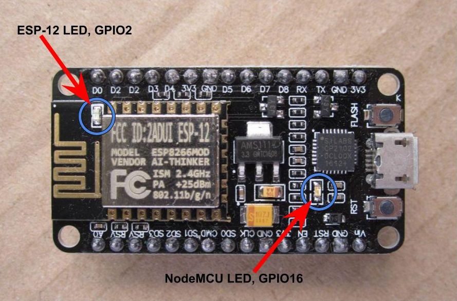
- GPIO2/GPIO16 also connected with Drain mode LED( Low level light up), identifiers are D4 and D0
- Ref: https://lowvoltage.github.io/2017/07/09/Onboard-LEDs-NodeMCU-Got-Two
- GPIO0/GPIO2/GPIO15 pins are used to determine in which mode ESP8266 will boot, so avoid using them as persistant pulling Input source.